From X-shaped to Cold Runner Layout with Virtual Molding

Download

From X-shaped to Cold Runner Layout with Virtual Molding

Upfront mold optimization for LSR applications with virtual molding In a four-cavity LSR mold, CVA Silicones, from France, was able to reduce scrap production, optimize thermal layout and avoid costly quality issues by using virtual molding software.

Authors:          

Matt Proske, SIGMA Plastic Services Inc.;

Laura Florez, Vanessa Schwittay, SIGMA Engineering GmbH

First Published in KGK 11/12-2014, Seite 6-9

The demand for liquid silicon rubber (LSR) products is growing. Particularly in the medical and baby care markets, its high thermal stability and very good physiological properties make LSR the material of choice for an ever increasing number of applications. However, molding LSR can be challenging: because it is a reactive material, the processing window is narrow and the scrap produced cannot be re-processed. Also a proper mold venting is paramount to avoid air traps. The position of welding lines and filling patterns, such as jetting, can affect the final product quality. Additionally, a proper mold tempering must be guaranteed during the whole molding cycle, in order to ensure a cost-efficient cycle time and a good product quality.

In order to maximize profit and reduce scrap, it is important to get a deep understanding of the complete process and to anticipate possible problems, including the flow and curing behavior, as well as the tempering conditions through the complete molding process.

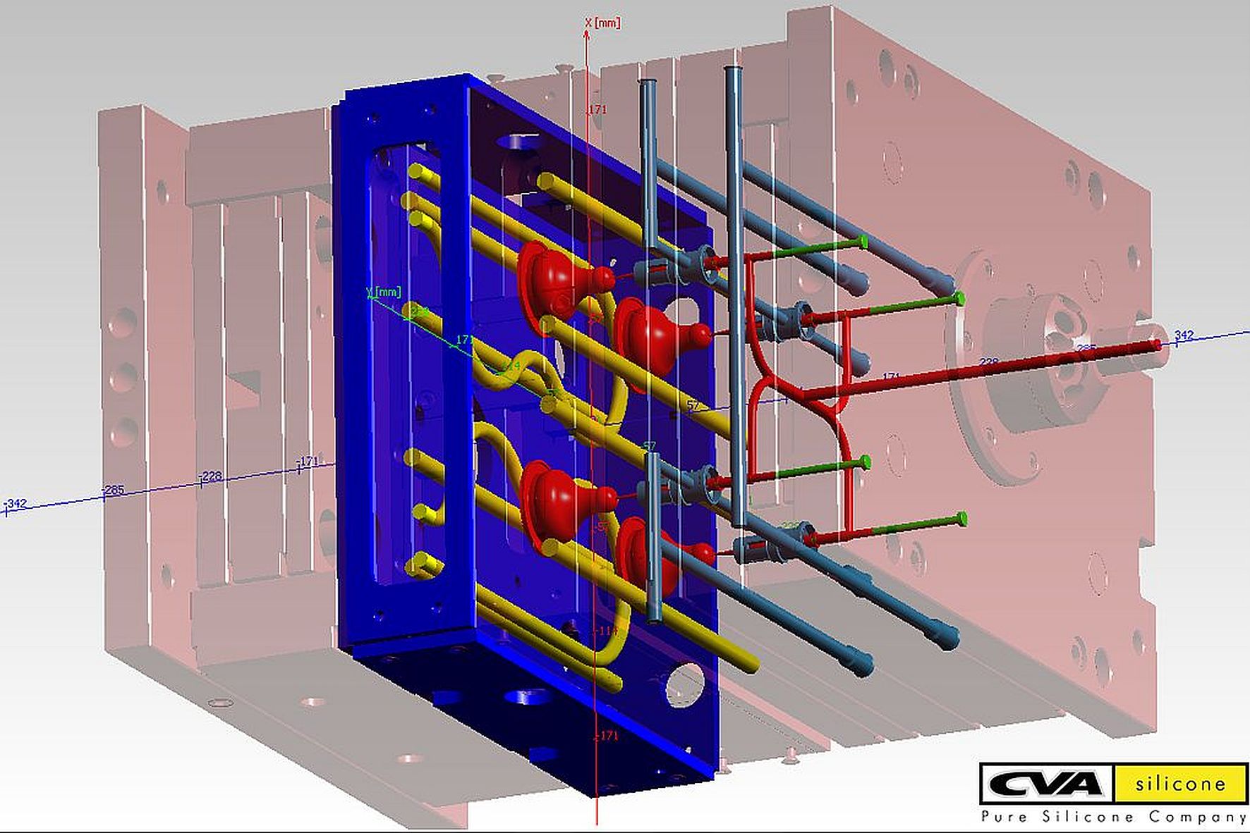
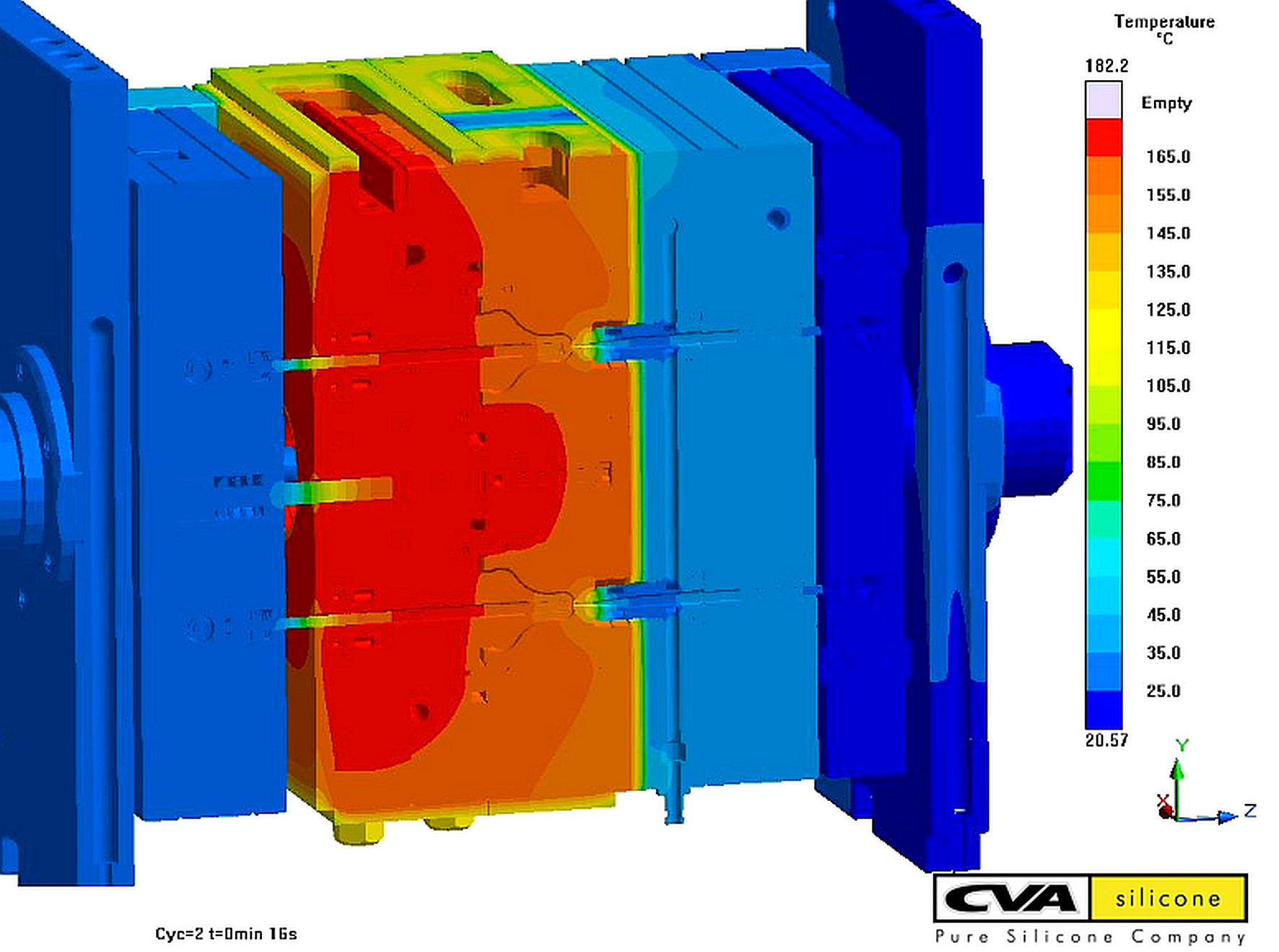
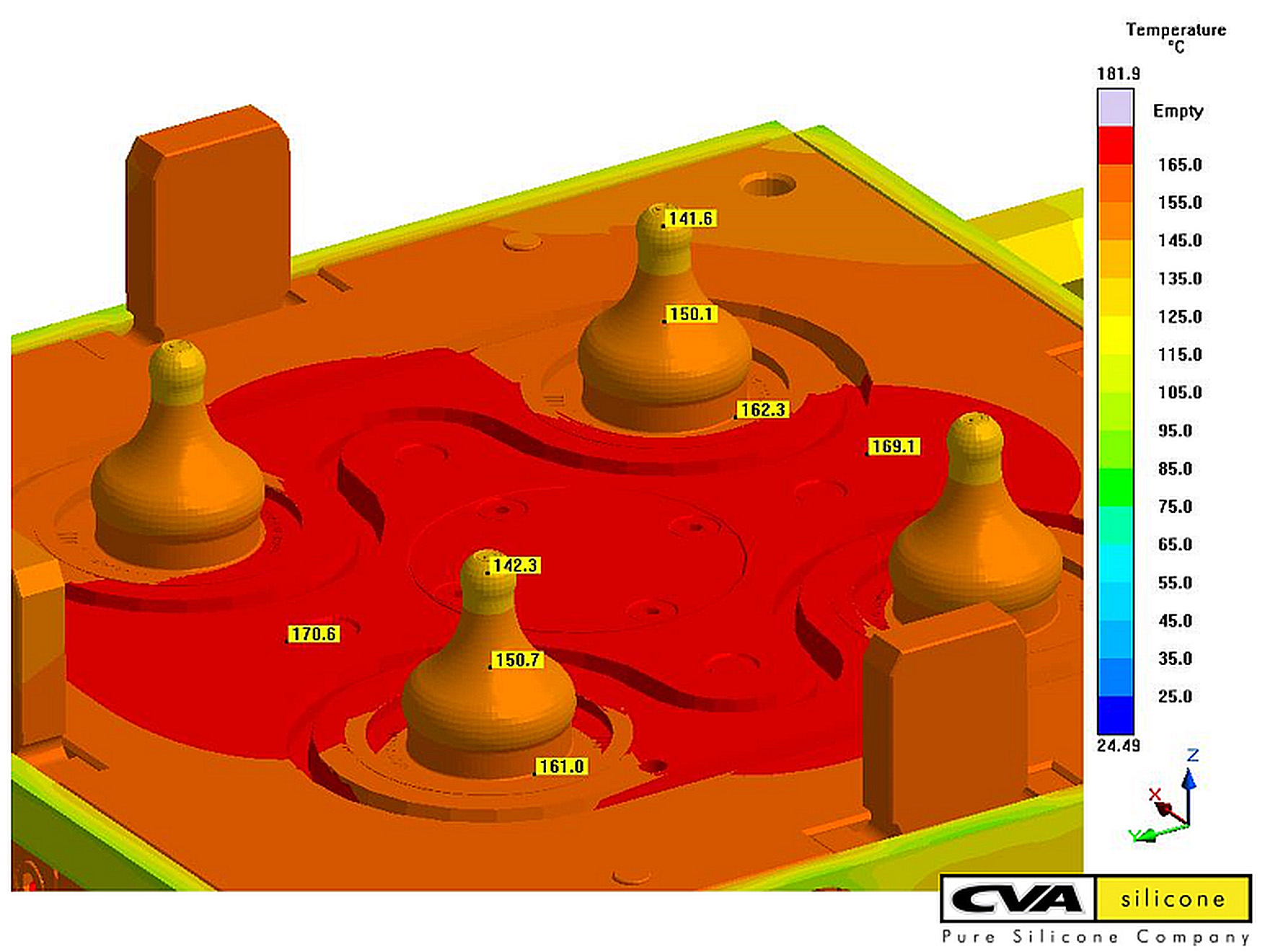
CVA Silicone, based in Saint Vidal, France, reached out to SIGMA to support the decision making process in a new four-cavity mold to produce silicon nipples. SIGMASOFT® Virtual Molding was used through each stage during mold development, to evaluate the runner design, the mold tempering and the overall efficiency of the molding system.

Finding the best runner  

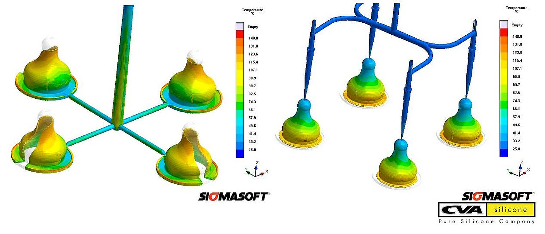
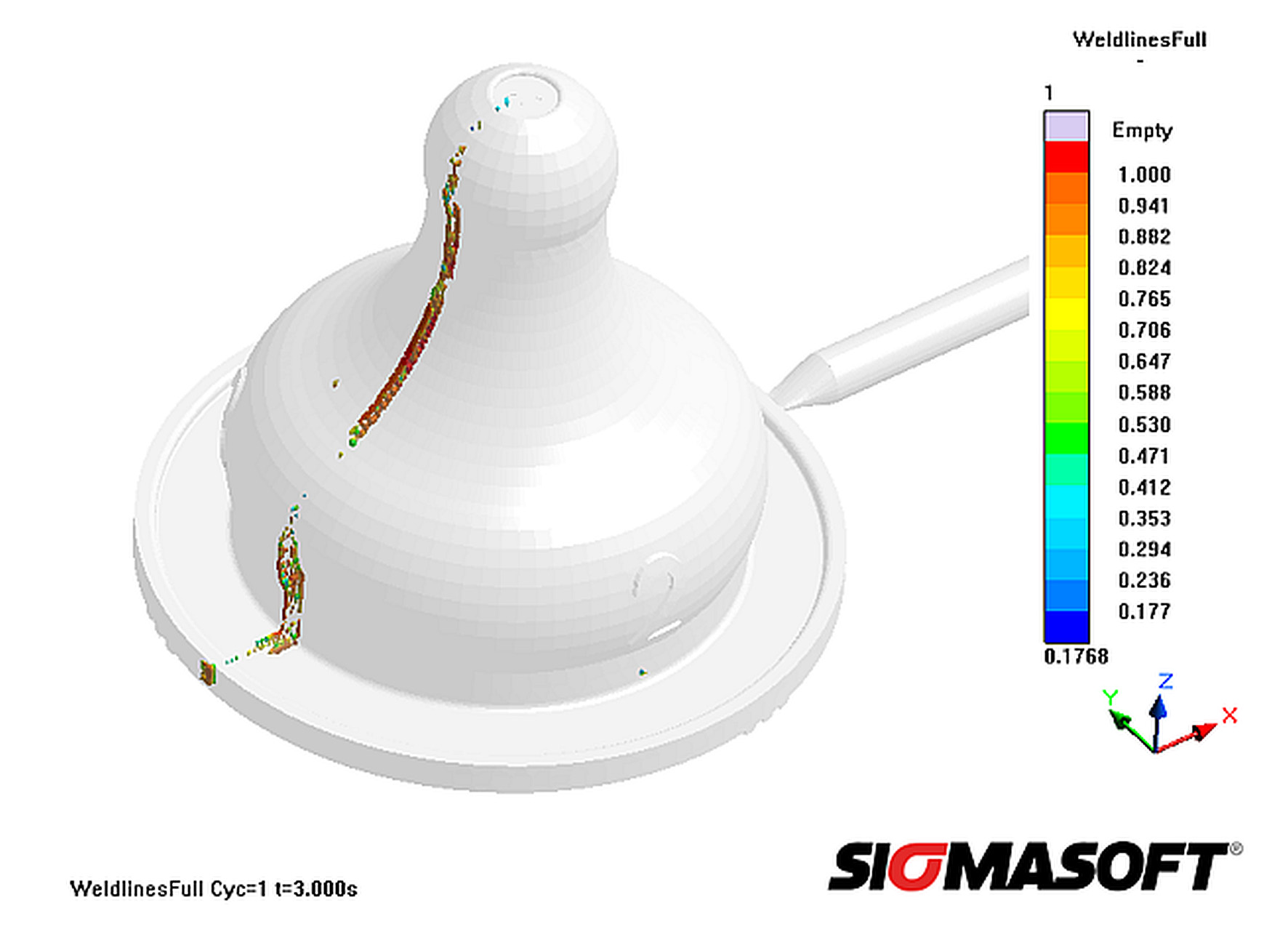
In a first approach, an X-shaped runner configuration, as seen in Figure 1a, was foreseen. As a traditional runner was to be used, the X-shaped minimized the scrap produced. The channels were cylindrical with a minimum diameter of 4 mm. Still, the runner volume represented 52% of the total shot volume. A first filling analysis with this configuration showed furthermore that weld lines would appear along the part, as seen in Figure 2, an undesirable outcome both for mechanical integrity and part aesthetics.

The alternative of using a cold runner was considered. In a cold runner, no material reticulation takes place, and therefore no scrap is produced. However, due to the additional investment required, the feasibility of this approach had to be carefully evaluated.

Figure 1a. Initial runner configuration with a conventional runner produced 52% of scrap. Figure 1b. An optimized cold runner layout eliminated scrap production. An iteration with SIGMASOFT® Virtual Molding produced the optimum layout

SIGMASOFT® Virtual Molding was used to evaluate different cold runner layouts. Several iterations were done virtually, where the parameters of balanced filling, pressure drop, flashing, clamping force and curing time were evaluated. In this iterative analysis, the mold was considered just as it works in reality, with all its components, each one with its own material properties. The optimal runner configuration, which minimized pressure drop and flashing while ensuring an optimum thermal performance, was found to be as presented in Figure 1b. The mold configuration used for the analysis is presented in Figure 3. The cycle time, energy efficiency and pressure required confirmed the alternative as economically viable, and an important reduction of 52% in volume per shot was achieved.

Figure 2. The initial X-shaped runner configuration, where the part is side-gated, produced undesired weld lines along the part.

Figure 3. The complete mold configuration, including the cold runner system, is used for the optimization.

Curing: the result of a complex thermal interaction

Once the optimum filling concept was found, an analysis of the thermal mold performance was approached. In this case, the objective was to obtain the real mold temperature, at each point and each step over the molding process, to predict the energy available for curing the LSR material.

The mold was reproduced just as in reality, with all components (as seen in Figure 3) over several molding cycles. The same production parameters as in reality were used: filling and curing conditions, even including the non-productive times between cycles. The mold starts from room temperature, and is tempered by the heating cartridges present. Several cycles are “run” virtually, just as in the injection molding machine, until the system achieves a quasi-stationary thermal state – the same that in reality would produce consistent part quality.

In Figure 4, the separation between the hot and cold regions of the mold is evident. Visualizing this behavior it was possible to improve the geometries of heater bands and to plan the positioning of sensors in the system.

Figure 4. Thermal distribution in the real mold. The separation between cold and hot mold regions is evident.

In Figure 5, the temperature distribution in the movable mold half is presented. This is the real temperature found after several molding cycles, produced by the interaction of the heating system, the mold material, the cold runner and the incoming cold melt. As seen, there is a significant temperature gradient in each part; while at the bottom of the cavity the temperature is around 160°C, at the nipple tip it was almost 20°C colder. This large temperature gradient induced variations in the curing behavior and increased the theoretical cycle time.

Figure 5. Real temperature distribution in the movable mold half. A significant gradient is built between the part´s bottom and tip.

For comparison purposes, the curing results achieved with a homogeneous mold temperature of 160°C are presented in Figure 6a. Under this ideal scenario, a curing time of 30s is required. In Figure 6b, the curing results produced with the real mold temperature are presented, making evident that at 30s only 43% of curing has been achieved on the part´s tip. Without this evidence the part performance would have been compromised, leading to costly decisions and most likely several blind iterations on the real mold would have been required to find the reason for part failure.  

SIGMASOFT® Virtual Molding can replace a real machine to do part and mold optimization in LSR injection molding, and important decisions about mold layout, productivity and part quality can be addressed based on a solid background. Several concepts can be tried in short times and at low costs, substantially reducing iteration in the production floor. Finally, resources are saved, increasing the profitability of production processes and liberating machine and personnel capabilities for further growth.

With the help of the software CVA Silicones could improve their parts and avoid quality issues. Additionally, as variations in mold design and process set-up could be safely tried on the computer upfront, costly mold iterations and trial-and-error at the start of production were saved as well.

Figure 6a. Curing degree at the nipple-tip after 30s with a homogeneous mold temperature of 160°C. Figure 6b. The real curing degree after 30s is only 43% with the mold temperature presented in Figure 5.